I bought from PCBway giftn modul. honesty i got beanpoint so i exchange with this module. I was interested with communication use this module. after i bought this module i must find out the tutotial to activated it . need DC step down , Screw terminal, DIYboard and another NRF24L01 module
see ya soon,
Minggu, 13 September 2020

Minggu, 08 Desember 2019
Project 20 How to use Relay Modul in arduino
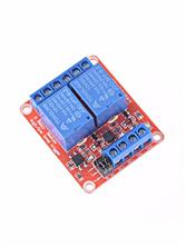
this time i will show how to turn on off the bulb light use relay, controlled with arduino.
simply modif blink example skecth from Arduino IDE example sketch code if you wanna more than 1 ch relay. today we use original blink led that makes D13 blink.
connect wire :
d13 with input relay
vcc 5v to vcc 5v relay
gnd to gnd relay.
make connection bulb dan power ac cord , another wire insert in blue connector of relay as switch.
upload the code
hear the relay ticking.. and the last connect the power ac cord to 220VAC.. you must see bulb blink
see ya.
Lamiono
Senin, 04 November 2019
Project 18 How to use LED Ring WS2812
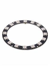
LED Ring 16 x WS2812 5050 RGB LED With Integrated Drivers, my plan to turn on with arduino .
not yet develop, need assistance...
the good news ny package was recieved susccesfully here the tracking report :


but unfortunatelly PCBWAY as this time is stockout i suggest refill soon or deleted that item due fast loading at web. do not show gift that you cannot get it. how a ptty..

not yet develop, need assistance...
the good news ny package was recieved susccesfully here the tracking report :

you can obtain this stuff in pcbway.com gift shop menu, click that menu as seen snapshot below:

but unfortunatelly PCBWAY as this time is stockout i suggest refill soon or deleted that item due fast loading at web. do not show gift that you cannot get it. how a ptty..

Senin, 28 Oktober 2019
Project 19 how to execute tiny 85 from digispark

Specification:
Supports Arduino IDE 1.0+ (OSX/Win/Linux).
Can be Powered By USB, 5v or 7-35v external power (automaticlly match).
A 5V/500mA Regulator is on board.
Built-in USB (Serial debugging).
6 I/O Pins (2 are used for USB only if your program actively communicates over USB, otherwise you can use all 6 even if you are programming via USB).
8k Flash Memory (about 6k after bootloader).
I2C and SPI (vis USI).
PWM on 3 pins (more possible with Software PWM).
ADC on 4 pins.
Power LED and Test/Status LED (on Pin0).
Colour: gray
Material: metal
size: 85 2.5*2cm
Selasa, 15 Oktober 2019
digital counter menggunakan IC 4026
Summary from eleccircuit dot com :
Modul ini menggunakan dua digit seven segmen common catoda atau dapat menggunakan single digit sevensegmen disesuaikan dengan layout PCBnya.
1. Cara kerja nya menghitung penekanan tombol clock atau dalam versi lain menggunakan ic 555 sebagai monostable dan atau pembangkit sinyal clock.
beberapa sumber referensi skema ada dari eleccircuit dot com menggunakan model pcb dari future kit.

cara pembuatan
cetak gambar layout PCB dibawah ini
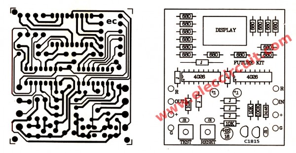
rangkai komponen pada papan tercetak lalu pasang baterai 6 volt dan geser posisi on saklarnya
maka sekarang akan tampil angka 00 pada display sevensegmen
tekan tombol test untuk menambah angka, tekan yombol reset untuk mengembalikan ke 00.
tekan terus sampai sepuluh maka IC2 mulai bekerja sebagai penghitung puluhan.
maksimal angka yang dapat dicapai adalah 99. yang kemudian bila diteruskan akan kembali ke 00.
bila berhasil sesuai dengan yang diharapkan maka rangkaian ini dinyatakan dapat berjalan normal.
another counter this photo from aisi555 dot com (Mr. nyoman Budi a.k.a Aho Cool)

he use microswtich to control the input without any transistors.
disana juga ada tanya jawab di blog nya.
here also scheme from circuitdigest dot com :
use only single sevensegment and single IC 4026.signal clock button refine with ic 555.
lets see design from circuitsgallery.com
Looks similiar with this bellow from gadgetronik.com
in future you may -
have nice try...
Selasa, 06 Agustus 2019
Packing G421237 tracknumber RV958178620CN throwback
here my story
in July 8th 2019
i got email that my order have been dispached by PCBWAY with correct tracknumber RV958178620CN by China Post i trusted they able to send and forward to INDONESIA POS but why they throwback my gift package , any new rules?
oh yeah before that PCBWAY mention that they changed the Express waybill for my order PCB (Purchase orders no G421237)

the other redeem gifts such as :
1. relay module (project 20) 1 pcs
2. Usb male bare connector 5V (project16) 1 pcs
3 2x8 cm DIY universal board (project 14) 10 pcs
4 3x7cm DIY Univ Board (project 13) 10 pcs
5. 2x8cm old stock (20181031) diy univ board 5 pcs
6. 3x7cm old stock (20181031) diy univ board 5pcs
i just realize that customocal here only allowed two kind product and price bellow $50 for free tax, if any above that will charge tax, If unable to pay tax, the stuff comeback to sender. :(
updated 2019-09-06
in July 8th 2019
i got email that my order have been dispached by PCBWAY with correct tracknumber RV958178620CN by China Post i trusted they able to send and forward to INDONESIA POS but why they throwback my gift package , any new rules?
oh yeah before that PCBWAY mention that they changed the Express waybill for my order PCB (Purchase orders no G421237)

the other redeem gifts such as :
1. relay module (project 20) 1 pcs
2. Usb male bare connector 5V (project16) 1 pcs
3 2x8 cm DIY universal board (project 14) 10 pcs
4 3x7cm DIY Univ Board (project 13) 10 pcs
5. 2x8cm old stock (20181031) diy univ board 5 pcs
6. 3x7cm old stock (20181031) diy univ board 5pcs
i just realize that customocal here only allowed two kind product and price bellow $50 for free tax, if any above that will charge tax, If unable to pay tax, the stuff comeback to sender. :(
updated 2019-09-06
Jumat, 02 Agustus 2019
Project 18 LED Ring 16 x WS2812 5050 RGB LED With Integrated Drivers
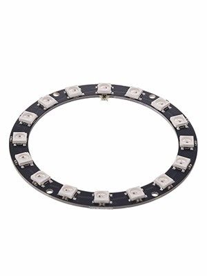
Shape model Ring
Use LED 16 Pcs 5050 RGB LED
IC Driver WS2812
Size : 68*68mm
Voltage : DC4-7V
Communication interface:Single-wire communication
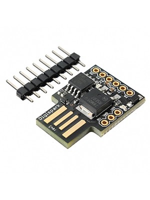
Digispark USB Development Board
The Digispark is an Attiny85 based microcontroller development board similar to the line, only cheaper, smaller, and a bit less powerful. With a whole host of shields to extend its functionality and the ability to use the familiar Arduino IDE the Digispark is a great way . Jump to INTO Electronics, or the when Perfect for the Arduino AN IS TOO Big TOO much or at The Digispark IS shipped the except for Fully Assembled at The TWO included Easy to Solder and headers. Here at The the specs are: Support for the Arduino the IDE at The 1.0+ (OSX / the Win / the Linux) the Power Via the USB or the Source External - 5V or 7-35v (Recommended 12V or less, Automatic Selection) the On-Board Regulator 5V 500mA Built-in the USB . 6 the I / O Pins (2 are Used for only the USB IF your Program actively communicates over the USB, otherwise you CAN use All. 6 the even IF you are Programming Via the USB) 8k the Flash Memory (the About 6K the After the bootloader) the I2C and the SPI (VIS the USI) the PWM ON 3 pins (More Possible the with Software the PWM) the ADC ON 4 pins power led and status
Specification:
Supports Arduino IDE 1.0+ (OSX/Win/Linux).
Can be Powered By USB, 5v or 7-35v external power (automaticlly match).
A 5V/500mA Regulator is on board.
Built-in USB (Serial debugging).
6 I/O Pins (2 are used for USB only if your program actively communicates over USB, otherwise you can use all 6 even if you are programming via USB).
8k Flash Memory (about 6k after bootloader).
I2C and SPI (vis USI).
PWM on 3 pins (more possible with Software PWM).
ADC on 4 pins.
Power LED and Test/Status LED (on Pin0).
Colour: gray
Material: metal
size: 85 2.5*2cm
Note: Light shooting and different displays may cause the color of the item in the picture a little different from the real thing. The measurement allowed error is +/- 1-3cm.
Price at tokopedia 20rb (almost 2 USD)
Langganan:
Postingan (Atom)